
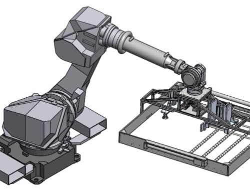
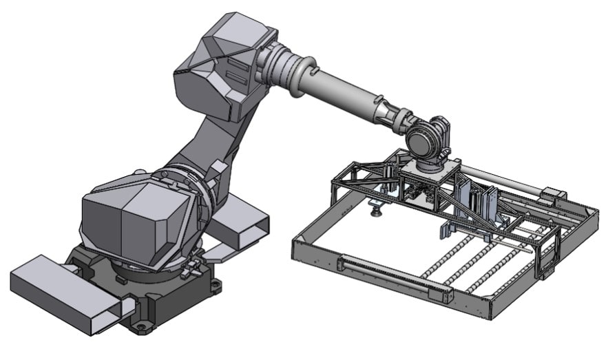
 3D CAD Modelling is a basic skill for every Mechanical Design Engineer. Most companies are dominated by the three prominent 3D CAD software, namely, SolidWorks, Pro-Engineer Creo & Autodesk Inventor. The good news is that being knowledgeable in any one of these is enough as all are based on almost the same CAD modelling concepts. However, being knowledgeable about any of the above DOES NOT mean you are a good Mechanical Design Engineer. Creative, out-of-the-box and revolutionary thinking are hallmarks of good designers.
I currently use SolidWorks for my designs and the below tips are referenced with SolidWorks features , but also apply for other 3D CAD Modelling Software.
Disclaimer: I have no relation to SolidWorks. If fact, their new renewal policy of paying for back-dated subscriptions is absolutely ridiculous and I am furious about it. We will not be arm-twisted & plan to move over to Creo or Inventor!
Tip #1: Do not make CAD models immediately.
Yes, that’s right! CAD models are useless if you don’t know what you want to do. Sketch, sketch, sketch … until you have a firm mental visualization of your concept.
Tip #2: Understand the two CAD Modelling Techniques
It’s important to understand the two basic CAD modelling Techniques.
Pull Type:
This is the one most users will be familiar with. You start with individual Parts (*.sldprt) and then assemble them into Assemblies (*.sldasm). Basically, you are “PULLING” parts into as assembly and BUILDING the design.
This technique is used in designs where each part has to be individually fabricated, and physically assembled together. Most system integration projects and “Assemblies” are done using technique.
Push Type:
This is an advanced skill and utilizes a lot of features like (indent, split, loft, etc) and also surface modelling. In this technique, you start with a part which is the end result and “split” it into numerous parts which are then “PUSHED” out as individual parts.
This technique is very helpful when designing products with organic shapes, plastic parts and when converting ID sketches into models.
Tip #3: Define a Naming Scheme
The next important thing after deciding your modeling technique is the naming scheme. A naming scheme is crucial for you to navigate thru your design and also make the naming of parts and assemblies systematic. If you have to navigate thru Bracket Assembly, Brkt Assy, Bckt and Bracket guide….you will have no idea where you are!
So, to keep it simple, follow an alpha-numeric code. A simple naming scheme that I like to use is Axx & Pxxxx scheme eg. A01 (Assembly 01) and P0101 (Part 1 of Assembly 1). So you can have 99 assemblies and 100 parts in each assembly. This is usually more than enough for typical designs, but if you anticipate more complexity, then just add in a few more numbers! This is simple, easy and systematic.
Tip #4: Follow the KISS rule … Keep It Simple and Stupid.
Less parts = Simple design = less complexity = high reliability
(I don’t think further explanation is required on this)
Tip #5: Always modular!
A modular design basically means that your design is structured and not a big mix of parts pulled/pushed as you keep making changes. A well-structured modular design in a PULL TYPE design will have a very simple and readable model tree. The top level should consist as much as possible, of Assemblies only. Avoid placing parts in top level assemblies as the exploded view in the detailed drawing can become pretty unsightly!
In a PUSH type design, a modular design might not be easy to do. However, you can structure your features by putting them in sub-folders. It will at least help you to navigate through your features easily.
Now that we are clear on the concept of modelling techniques, naming schemes and modular design methodology, we can dive in to the CAD Modelling techniques.
Tip #6: Use Datums
The simple DATUM is one of the most under-utilized but most efficient feature in a CAD model. Unfortunately, most CAD systems do not emphasize this feature much, mainly because it makes the CAD Model look unnecessarily complex thereby scaring off new users.
However, the DATUM is fundamental to any design and should never be neglected.
An essential help that the DATUM provides is that it aligns your model to the view ports. A lot of designers simple forget to do this and they can have their designs “FIXED” anywhere in the coordinate system. When required to take good photos of your model, it always appears skewed.
Apart from the view port alignment, the first feature that you model (typically and extrusion or revolve feature) gets defined with respect to the PRIMARY, SECONDARY and TERTIARY datums. These three datums are important when you need to have GD &T (Geometric Dimensioning and Tolerancing). These three datums are also the “machining references”; crucial for manufacturing.
So, when extruding / revolving the first feature, keep in mind, the location of the datum. The direction of extrusion (mid-plane, towards and away) can easily change the datum plane orientations. So, the first feature is the FOUNDATION; make sure it is done properly and the Primary, Secondary & Tertiary Datums get properly defined.
Tip #7: Use Sheet-metal Features for Sheet-metal design
When design for sheet-metal parts, do NOT extrude a big block, shell it, and put the fillets and then convert it to a sheet-metal part. This is the WORST way to design sheet metal parts. SolidWorks offers a feature to CONVERT a solid model into a Sheet-metal part; however, I strongly recommend that if your part is a sheet-metal, start with the Sheet-Metal feature (base flange). Then you use all the sheet metal features without errors. Most importantly, now you can see the development (SW calls it “Flat Pattern”) and bending lines easily. This is a very good function for sheet metal fabricators.
Tip #8: Make sure your sketch is fully constrained
Sketching properly is also very important and extremely efficient. SolidWorks has a very simple and efficient visual feature that allows us to see if a sketch is properly constrained. If the sketch features are BLACK, this means it is properly constrained. If you see any sketch features (even a vertex) in BLUE, it means that the feature is not constrained. You can physically move it with the mouse to see which degree of freedom needs to be constrained. I strongly recommend that you constrain all sketch features as this can adversely affect you later when making changes to the design.
Tip #9: Link Dimensions for greater efficiency
Linking dimensions is also a very useful feature in the Sketch tools. For example, if you need to design a square feature with the wall thickness to be the dimension, you will need to add at least 2 dimensions which are the same. To maintain your design intent, you have to regularly change both dimensions (as they are related) to ensure the same wall thickness. To simplify matters, SW allows you to link the dimensions. So changing one, automatically changing the other; this reduces your work-load significantly…not to mention errors!
Tip #10: Insert Fasteners into the assembly
I must confess that I don’t like to do this, but I have learnt that it’s better to be put in that extra effort now, than to impact the project at a later stage. However, I strongly suggest that this is done in a separate configuration. This prevents the assembly drawing and Assembly BOM from becoming abnormally big and messy.
So, after completing a sub-assembly in a module, evaluate the model using the Hole Alignment Check in the Evaluation Ribbon. It is a very effective check and it’s better to catch a mis-alignment issue now and save time & money rather than find out after fabrication of parts and assembly. Then you can use the SW Toolbox to add in spring washers, flat washers, screws, dowel pins, retaining rings, etc.
This (pain-staking) process gives you a good idea of the assembly process, allows you to check the tool accessibility & also helps you to prepare the fasteners list for the Bill of Material (BoM). After all, the last thing you need is an awesome design which cannot be assembled without using specially modified tools or specially sized fasteners.
Tip #11: Learning from YouTube
SolidWorks has built in features for Plastic design features like bosses, inserts, ribs, lip/groove. If you are not familiar with this, I strongly advise learning from YouTube Videos to study each feature when you need to use it. Please be humble and don’t think you can figure out the features and it’s subtleties without help. A YouTube video is a very fast and effective way to learn the feature and how you use it appropriately.
Tip #12: Interference Check
It is always important to do an Interference Check when you are close to finalizing the Assembly design. It a simple fast check which SolidWorks provides but is usually ignored.
Tip #13: Use Simulation Wizard
 And last but not the least, use the Simulation Wizard to check for bending, stress points and load bearing. The Simulation Wizard gives a simple presentable analysis using the Distortion Energy Theory. This calculates the Von Mises stress of your design and the max stress should be less than the Von Mises Stress. The advantage of doing this simulation forces you to add Material properties of each part.
This simulation study is very helpful when I need to choose the thickness of sheet metal parts. As you probably know, changing the sheet metal thickness can significantly change the load bearing capacity. But, choosing excessively thick sheet metal, can incur high cost of material and process.
Tip #14: Learn from my mistakes
And there you have it! I have greatly benefited from these few CAD Modelling tips. Many of the above tips have been learnt the hard way at the expense of significant embarrassment!! So please learn from my mistakes and I hope this article contributes to the budding designers in the engineering community!
Please feel free to contact me if you have any additional tips, questions and comments.
Abhijit Rege
E-mail: enquiry@synergydesignsolutions.com.sg


